Skip to content
< All Topics

Siemens Fetch & Write

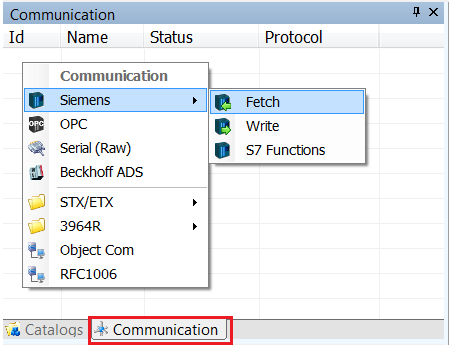
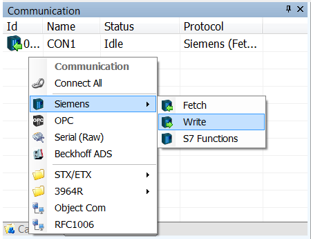
The following section shows how to use the Siemens Fetch and Write protocol to program and run the basic psychics model example.
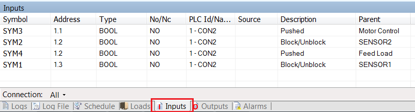
  • Click on the Communications tab on the right of the Experior window, just below the Catalogs tab
  • Now right click on the first line and select Siemens and then click Fetch
  • Next, on the second line down, do the same again only this time select Write
  • Now it is time to configure the two communications devices
  • Select the Fetch device first and fill out the Properties like so
  • Next select the Write device and configure the Properties like so
  • Now to setup the I/O for the devices that require it. For the moment just the addresses will be used
  • The I/O is laid out below along with the associated items:
INPUTS
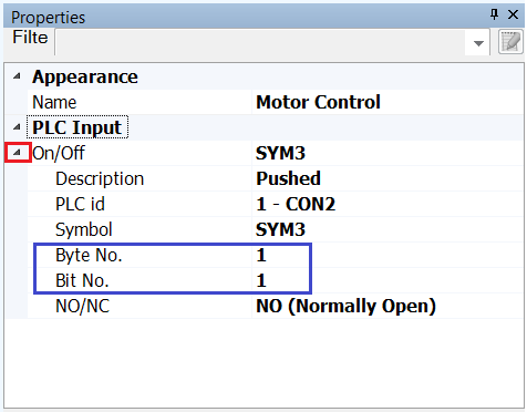
1.1	Motor Control “Switch”
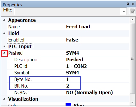
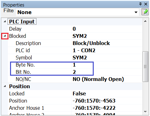
1.2	Feed Load “Button” & Feed Load “Sensor” (2nd Sensor in system)
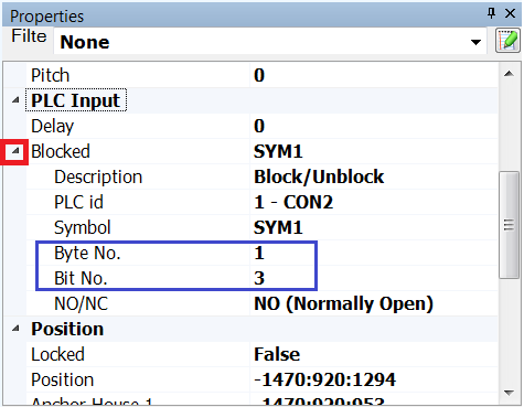
1.3	Load In System “Sensor” (1st Sensor in system)
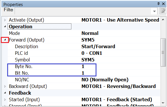
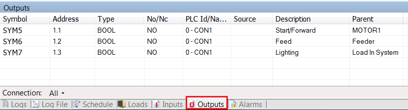
OUTPUTS
1.1	Motor Drive Control
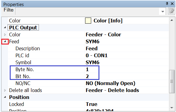
1.2	Feeder “Feed Load” Control
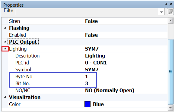
1.3	Load In System “Lamp”
  • Let’s set up the Inputs first
  • Select the switch called Motor Control in the Control Panel
  • In the Properties panel, below PLC Input expand the properties by clicking the arrow to the left of where it says On/Off
  • Enter the Byte No. as 1 and the Bit No. as 1
  • Now select the push button Feed Load
  • In the Properties scroll down to PLC Input and expand the section by clicking the arrow to the left of where it says Pushed
  • Enter the Byte No. as 1 and the Bit No. as 2
  • Now select the second sensor that was added to the model earlier
  • In the Properties scroll down to PLC Input and expand the section by clicking the arrow to the left of where it says Blocked
  • Enter the Byte No. as 1 and the Bit No. as 2
  • Now select the first sensor that was added to the model
  • As before scroll down to PLC Input in the Properties and expand the section called Blocked by clicking on the arrow
  • Enter the Byte No. as 1 and the Bit No. as 3
  • Now, if the Inputs tab at the bottom of the screen is selected, the list of the inputs in the model can be viewed
  • Now to add the Outputs to the system
  • Select the Motor by clicking any of the red arrows in the model
  • In the Properties scroll down to where it says Operations and expand the section for Forward (Output) by clicking on the arrow to the left of it
  • Enter the Byte No. as 1 and the Bit No. As 1
  • Now select the Feeder, that is the triangle/arrow located on the first straight that was added to the model
  • Scroll down the Properties to the section PLC Output and expand the section for Feed by clicking on the arrow to the left of it
  • Enter the Byte No. as 1 and the Bit No. As 2
  • Lastly select the Lamp in the Control Panel
  • In the Properties scroll down to PLC Output and expand the properties under Lighting by clicking the arrow to the left of it
  • Enter the Byte No. as 1 and the Bit No. As 3
  • Now if the Outputs tab at the bottom of the screen is selected the list of the outputs in the model can be viewed
Was this article helpful?
How can we improve this article?
Please submit the reason for your vote so that we can improve the article.